


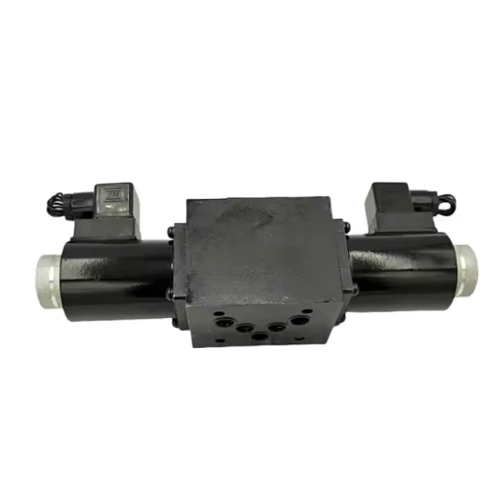
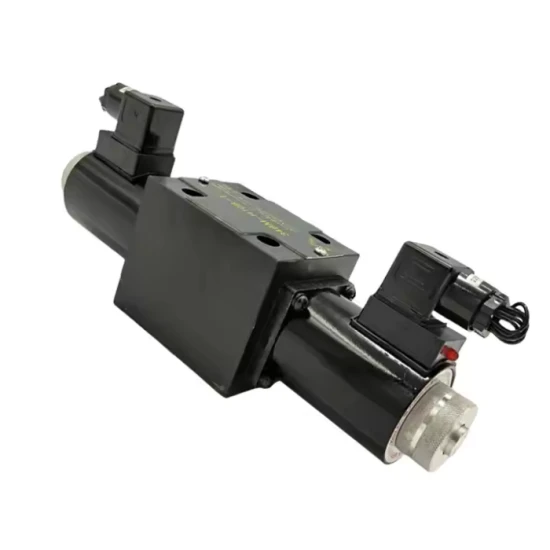
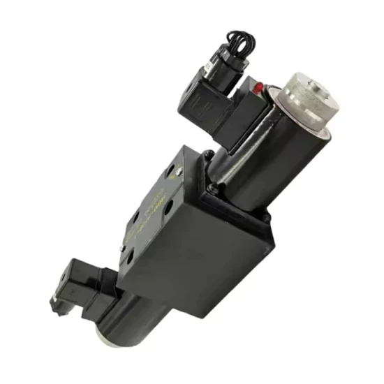


34EO-H10B-T Double Ended Hydraulic Solenoid Valve
This is a three position four-way, O-type center function, dual solenoid control, spring centering reset, dry solenoid, rated flow of about 38 L/min, hydraulic solenoid directional valve with DIN standard plug.
34EO-H10B-T
34: The "position" and "passage" of the valve
The first number 3 represents the number of working positions of the valve core. This is a three position valve. Usually includes: left position (electromagnet A is powered), center position (electromagnet A/B is not powered), and right position (electromagnet B is powered).
The second number 4 represents the number of main oil ports for the valve. This is a four-way valve. A standard four-way valve has four main oil ports: P (pressure oil inlet), T (return tank port), A (actuator working port A), and B (actuator working port B).
E: Electromagnetic type or power supply specifications.
E usually represents a dry electromagnet (coil isolated from hydraulic oil). This is the most common industrial electromagnet, with a long lifespan and coils that are not easily contaminated.
Sometimes there is also implicit voltage information, but it needs to be confirmed in conjunction with the entire model or sample (commonly 24V DC or 110V AC, etc.).
O: The middle position function of the valve (the oil circuit connection method of the middle position of the three position valve).
O is the standard O-type median function. Under this function, when both electromagnets are powered off, all four oil ports P, T, A, and B are closed (not connected to each other).
Features: The actuator (oil cylinder or motor) is locked in the valve center position and cannot move, with good load-bearing and pressure holding performance. But the oil discharged by the pump must be unloaded through the relief valve, which may generate heat.
H: Nominal diameter or interface size.
H usually corresponds to 3/8 inch imperial interfaces (such as SAE O-ring flat sealing interfaces) or metric threads such as M14 × 1.5/M18 × 1.5. H10 as a whole is more common.
10: Nominal flow rate. This represents 10 US GPM (gallons per minute), which is approximately equal to 38 L/min. This is the rated flow rate of the valve designed at standard pressure differential (usually 7 bar). In actual use, the flow rate should not exceed this value too much, otherwise pressure loss and heating will increase dramatically.
B: Valve core structure or spring centering method.
B usually represents a three position valve with dual solenoid control and spring centering reset. One end has an electromagnet, and the middle is reset by two centering springs.
T: Electrical interface form or sealing material.
The common explanation for T is: "DIN 43650 Form A" standard electrical plug (also known as "metric plug"). This is a widely used industrial standard waterproof plug with built-in LED indicator light (used to display whether the electromagnet is powered).
Comprehensive Interpretation and Application
This is a three-position, four-way, O-type center function, double solenoid-controlled, spring-centered reset, dry solenoid, hydraulic solenoid directional valve with a rated flow of approximately 38 L/min and a DIN standard plug.
Typical Working Principle:
Electromagnet A is energized: The spool moves to the left position. The oil circuit is connected as follows: P → A, B → T. The hydraulic cylinder extends or the motor rotates clockwise.
Electromagnet B is energized: The valve core moves to the right position. The oil circuit connects as follows: P → B, A → T. The hydraulic cylinder retracts or the motor reverses.
Both solenoids are de-energized (normal position/neutral): Under spring force, the spool returns to the neutral position (O-type). Ports P, T, A, and B are fully sealed. The cylinder/motor is locked, and system pressure is set by the relief valve.
Advantages and disadvantages of the neutral function (O-type):
Advantages:
Excellent locking performance: Suitable for applications where the cylinder needs to stop accurately at any position and bear certain loads (e.g., intermediate stops in lifting mechanisms).
Good pressure retention: The oil cylinder can maintain pressure when ports A and B are sealed.
Disadvantages:
Significant reversal shock: When transitioning from a stationary state to starting or reversing, sudden high-pressure or return oil connection in both chambers of the hydraulic cylinder may cause impact.
The pump needs to be unloaded: When the pump is in the neutral position, the incoming oil has no way to discharge and must return to the oil tank through the relief valve, resulting in energy loss and system heating.
Common applications:
Cylinder control requiring bidirectional action and precise locking at the intermediate position (e.g., injection molding machine mold closing cylinders, press lifting cylinders, and support leg cylinders in construction machinery).
A hydraulic motor system requiring three-position control (forward-stop-reverse).
Hot Tags: 34eo-h10b-t double ended hydraulic solenoid valve, China 34eo-h10b-t double ended hydraulic solenoid valve manufacturers, suppliers, hydraulic valve inspections, hydraulic valve keys, medium pressure hydraulic valve, purchase hydraulic valve, hydraulic valve pistons, hydraulic valve barcodes
 Electric Hydraulic Directional Valve 24EYO-H20B-T
 Hydraulic Pilot Relief Valve DR6DP1-5X/150YMV
 DG4V-3-6C-M-U-H7-60 VICKERS Solenoid Valve DG4V-3-2C...
 MVP30.14D-04S5 MVP60.72D-06S8 Sany Small Excavator M...
 DBW10B-1-50B/315 6CG24N9Z5L Electromagnetic Pilot Re...
 DSG-01-3C2-D24-N1-50NB Solenoid Valve
Send Inquiry
